
CCTV & Computer Cable Manufacturing Process
Flow Chart Diagram
Step-wise Manufacturing Process
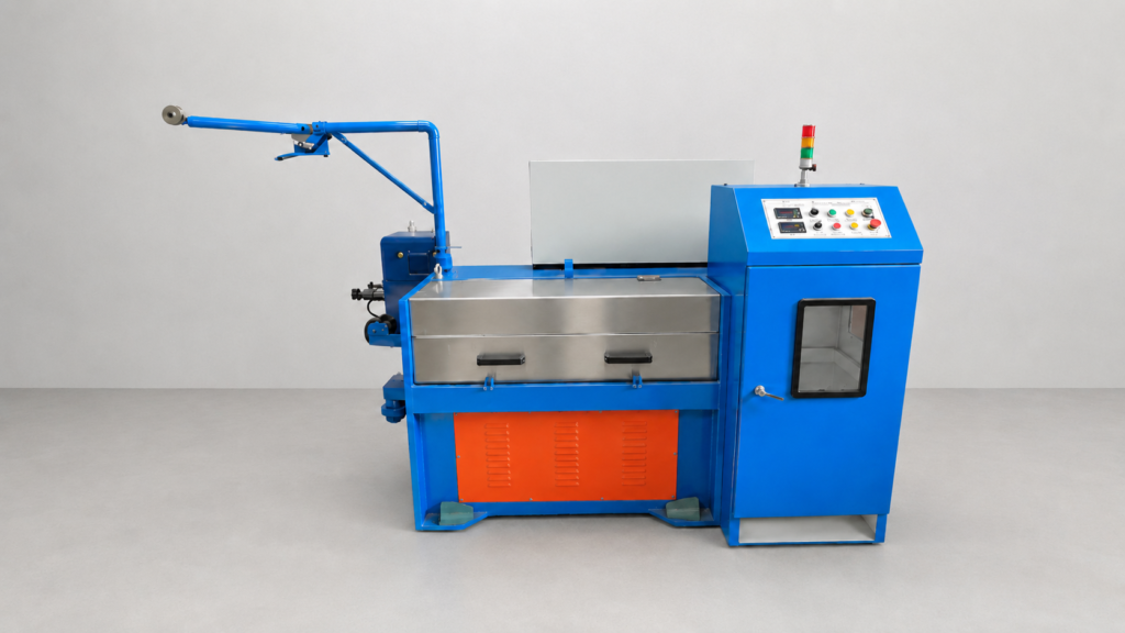
Step 1 – Wire Drawing Machine
- Copper rod is drawn into the required conductor size.
- Diameter is reduced through drawing dies.
- Smooth and uniform conductor is produced
Output: Fine Copper Wire
Step 2 – Annealing Process
- Drawn wire passes through annealing.
- Improves flexibility and conductivity.
- Removes hardness generated during drawing.
Output: Soft Annealed Copper Wire
Step 3 – Core Insulation Line
- PVC or PE insulation is applied over conductors.
- Different colors are used for identification.
- Insulation thickness is controlled automatically.
Output: Insulated Conductors
Step 4 – Core Twisting
- Two insulated conductors are twisted together.
- Mainly used for computer cables and data transmission.
- Improves signal stability.
Output: Twisted Pair
Step 5 – Cabling Process
- Multiple insulated cores are assembled.
- Cable structure is formed according to specification.
- Fillers may be added if required.
Output: Multi-Core Cable
Step 6 – Shielding Process
- Aluminum foil shielding applied.
- Copper braiding added for EMI protection.
- Essential for CCTV and Data Cables.
Output: Shielded Cable
Step 7 – Outer Sheathing Line
- PVC outer jacket is extruded over the cable.
- Provides mechanical protection.
- Available in different colors and grades.
Output: Finished Cable Structure
Step 8 – Printing & Meter Marking
- Brand name printed on cable.
- Size, voltage rating and meter marking added.
- Online printing during production.
Output: Identified Cable
Step 9 – Quality Testing
Tests include:
- Conductor Resistance Test
- Insulation Resistance Test
- Spark Test
- High Voltage Test
- Diameter Check
- Shield Continuity Test
Output: Approved Quality Cable
Step 10 – Coiling & Packing
- Cable wound into coils or drums.
- Length measured automatically.
- Packed for dispatch.
Output: Finished CCTV & Computer Cable